Line Scanner
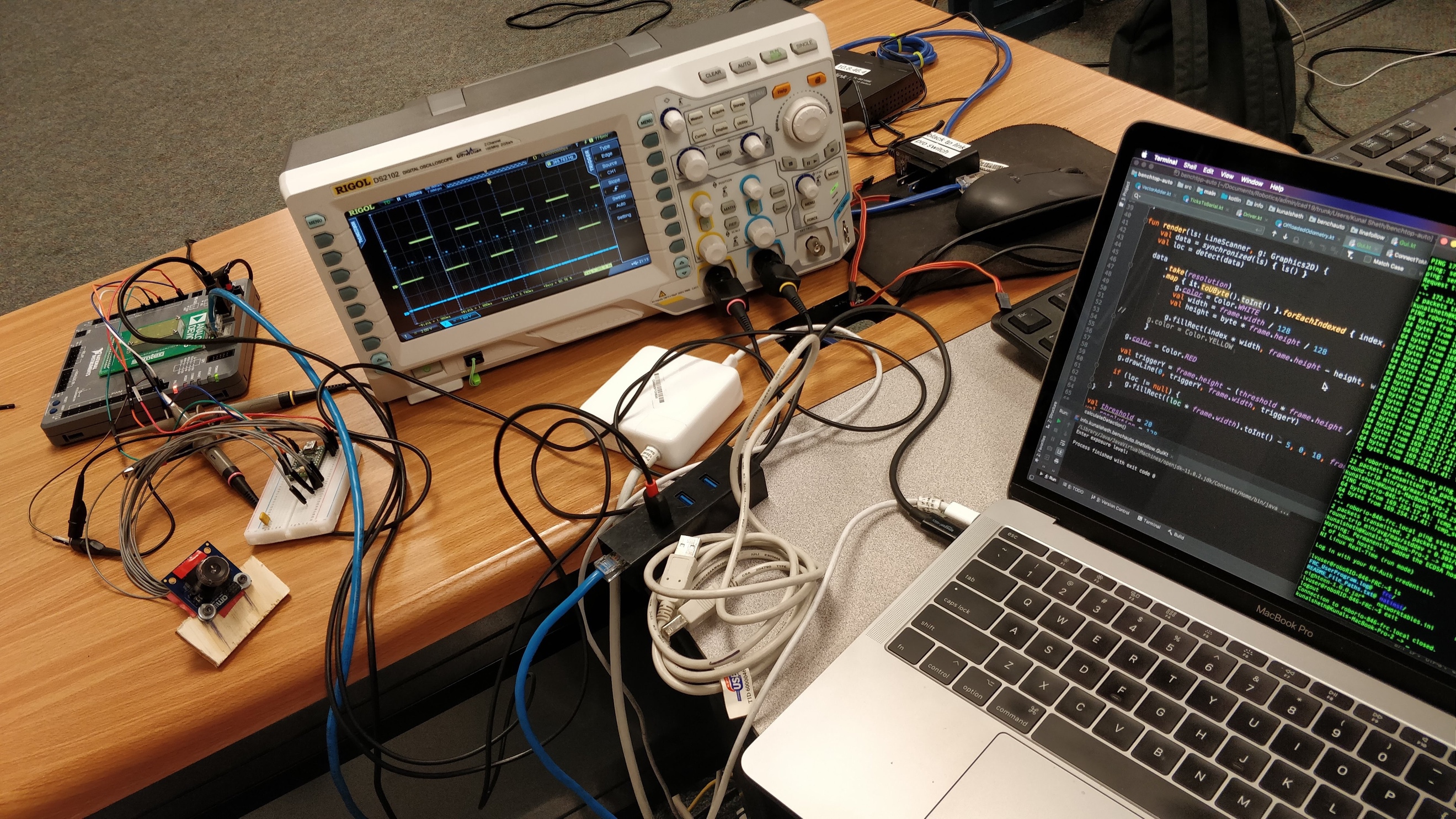
While my High-Frequency Odometry boards are good, they aren’t perfect. Using drivetrain encoders alone, I couldn’t account for wheel slip. And that’s why I started my Line Scanner project. My Line Scanner project uses a 128-pixel light-to-voltage array for real-time, low- footprint “computer vision.” It allows me to detect the robot’s field-relative position and to reset my odometry board’s accumulated positioning error. Due to hardware limitations and numerous manufacturer driver issues, I had to develop my own form of two-way communication between my microcontroller and the robot’s main processor. (I didn’t want to have to reprogram the microcontroller just to change exposure and vision thresholding values.) In this picture, I’m using an oscilloscope to debug the protocol I developed.
Here my Line Scanner is detecting the piece of white tape on the floor. While the readings look clean in this video, I was worried about random reading spikes and noise affecting a naive highest-peak vision tracking algorithm. So, I made my tracking code noise-resistant—taking into account a peak’s width in combination with its height.
Once again, my Line Scanner is detecting the piece of white tape on the floor. Because I am only processing 128 bytes of image data every cycle, I can run a real-time control loop directly off of the line’s position, with minimal computational overhead.