High-Frequency Odometry Board
Before robots can start following trajectories, robots need to know their cartesian position. In past years, my robotics team’s odometry was consistent, but not accurate. This made trajectory following possible but time-consuming as we kept having to “fudge” our waypoints. In 2018, I wanted to fix this strange behavior. So, I started by modeling the robot’s drivetrain and cartesian tracking algorithms in Excel. With every position tracking algorithm I tried, there was always a significant amount of drift. The only solution I found to improve encoder-only odometry was to substantially increase the update frequency—say, every encoder tick. Thus, I started my High-Frequency Odometry Board project.
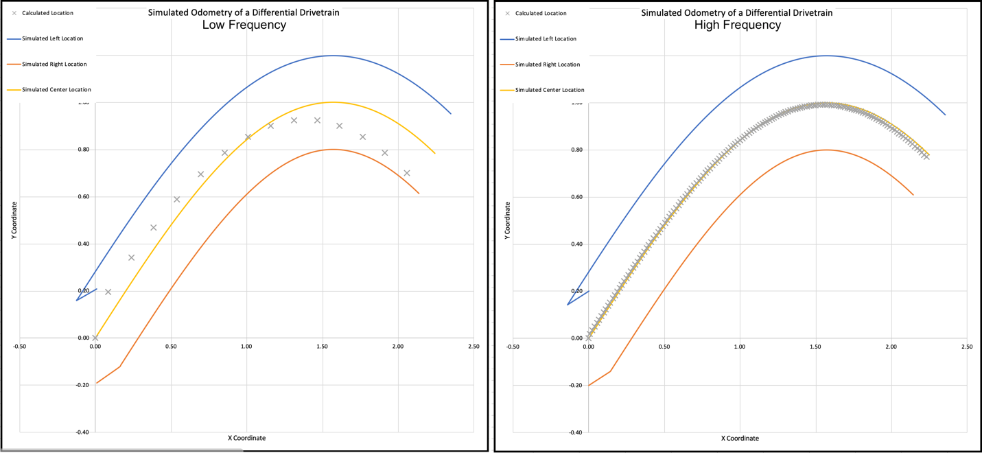
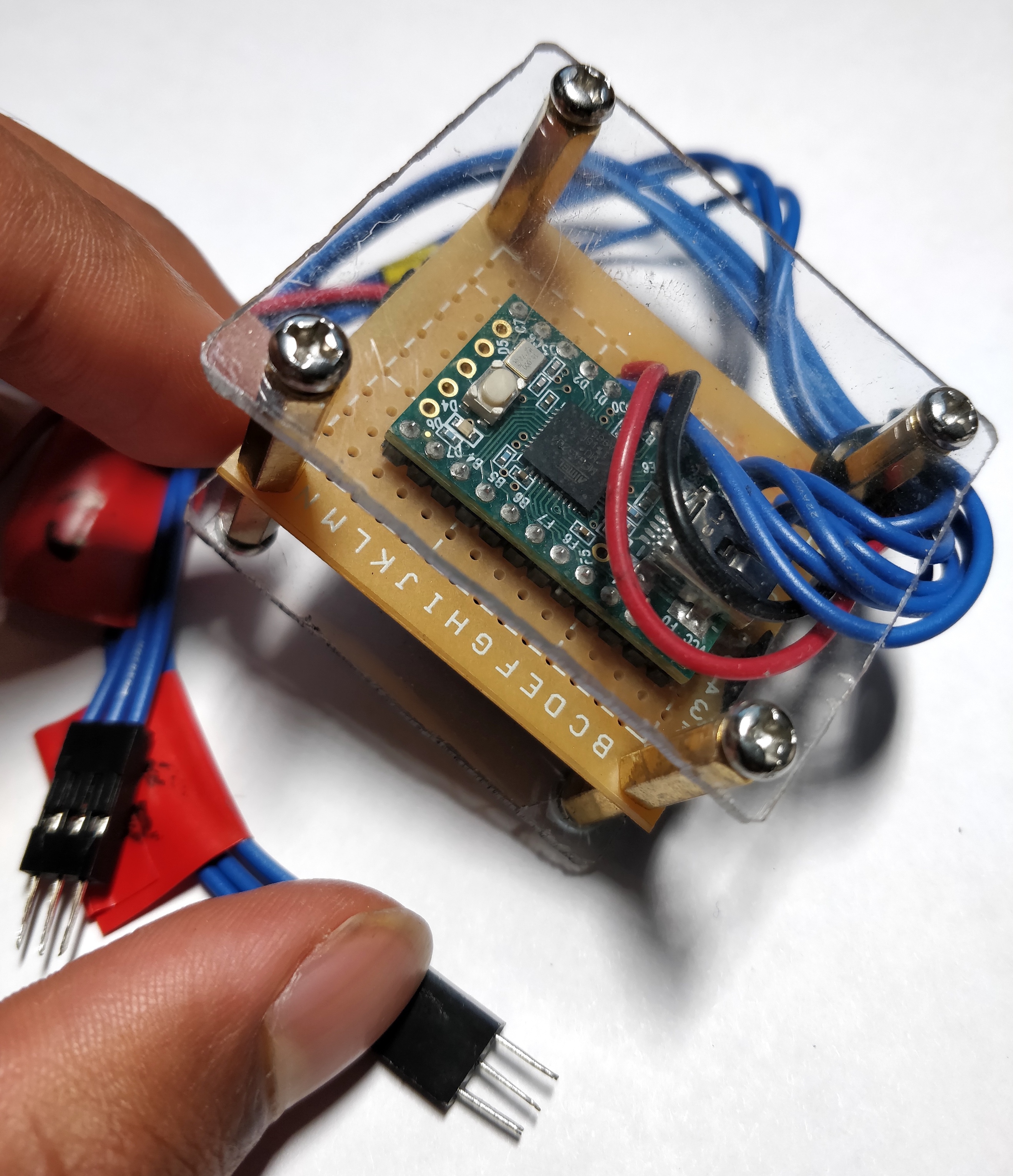
The laptop shows where my odometry board prototype locates my model drivetrain. My USB Control Systems can handle multiple motors and sensors simultaneously. Using two motors and two encoders, I build a model differential drivetrain on my desk! With this setup, I began prototyping my High Frequency Odometry Boards. But, my goal of recalculating position every encoder tick proved harder than initially expected.
With encoder ticks streaming in at up to 40kHz, running the trigonometric functions necessary for a naive vector addition odometry algorithm is not possible. The 16MHz, 8-bit microcontroller I was using couldn’t handle it, even after I refactored to use fixed-point math and stored a SIN lookup table in ROM. To reach the frequencies I wanted, I took a new approach—rotation matrix tracking. I store the XY coordinates of the left and right wheel separately. Each left encoder tick rotates the left coordinate about the right, and vice versa. Since rotation matrices use delta-theta (instead of the robot’s actual bearing), I can cache the necessary SIN and COS values. Every encoder tick interrupt, the microcontroller only has to multiply and add—way faster than SIN and COS!
Using my High-Frequency Odometry board for feedback, the robot follows a pre-recorded list of waypoints as fast as it can. I also wrote all the waypoint following and motion profiling code running in this video. (The ending target is taped on floor in the left corner, not pictured.) While this project made encoder-only odometry far more accurate, the robot still accumulated some error over time, likely due to wheel slip.